Connecting the nRF24L01+
to the Raspberry Pi
![]()
Boring specs on the Pi
- Broadcom 2835 SoC with a 700 MHz ARMv6 core
- 256/512 MB RAM
- HDMI output
- 2xUSB + USB Network on Model B
- Analog audio output
- GPIOs, UART, I2C and our friend SPI
- SD card slot for software
Boot process - 1
- SoC internal ROM
- Mounts FAT32 SD card
- Loads bootcode.bin to L2 cache
- Starts GPU
- GPU loads start.elf (2.6 MB!)
- Loads config.txt
- Configures memory using fixup.dat
- Starts ARM CPU
Boot process - 2
- Depending on config.txt loads kernel.img
- Everything is proprietary except the Linux kernel :(
- Example cmdline.txt:
dwc_otg.lpm_enable=0 console=ttyAMA0,115200 kgdboc=ttyAMA0,115200 console=tty1 root=/dev/mmcblk0p2 rootfstype=ext4 elevator=deadline rootwait
Raspbian - 1
- Distribution based on Debian
- Comes as a simple image you can
ddto an SD card - 56 MB FAT32 partition
- 1.8 GB ext4 partition with ~300 MB free
mount -o loop,offset=0x400000 -t vfat raspbian.img /mntmount -o loop,offset=0x3C00000 -t ext4 raspbian.img /mnt
Raspbian - 2
Contents of the fat partition:
-rwxr-xr-x  1 root root   17808 Jun 19 11:08 bootcode.bin*
-rwxr-xr-x  1 root root     142 Jul 26 12:50 cmdline.txt*
-rwxr-xr-x  1 root root    1180 Jul 26 12:50 config.txt*
-rwxr-xr-x  1 root root    2024 Jun 19 11:08 fixup_cd.dat*
-rwxr-xr-x  1 root root    5882 Jun 19 11:08 fixup.dat*
-rwxr-xr-x  1 root root    8832 Jun 19 11:08 fixup_x.dat*
-rwxr-xr-x  1 root root     137 Jul 26 14:44 issue.txt*
-rwxr-xr-x  1 root root 9610248 Jun 19 11:08 kernel_emergency.img*
-rwxr-xr-x  1 root root 2803520 Jun 19 11:08 kernel.img*
-rwxr-xr-x  1 root root  468536 Jun 19 11:08 start_cd.elf*
-rwxr-xr-x  1 root root 2689268 Jun 19 11:08 start.elf*
-rwxr-xr-x  1 root root 3656516 Jun 19 11:08 start_x.elf*
So what are all these files good for?
Raspbian - 3
- gpu_mem is default set to 64 MB
- *_cd (cut down) used for gpu_mem=16. Missing OpenGL ES + friends
- *_x (xtra) is with extra (unstable) features. E.g. video codecs
bootcode.binunderstands a couple of config.txt options:
start_file=start_x.elf
fixup_file=fixup_x.dat
gpu_mem=16
Raspbian - 4
We have pre-configured an image with DHCP and SSH enabled
Login: pi / hamster
Two Linksys APs (Rasp Pi 1 and 2): admin / hamster
Use raspi-config to expand the file system
External connector on the Pi
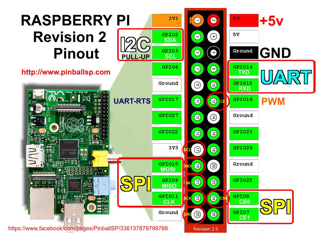
GPIO on the Pi - 1
- Simple digital input/output
- 3v3 levels
- Controlled via sysfs
- No over-voltage protection - careful!
GPIO on the Pi - 2
| ... | export GSYS=/sys/class/gpio |
| Exporting a pin 25 as output: | echo 25 >$GSYS/export |
echo out >$GSYS/gpio25/direction | |
| Setting it high: | echo 1 >$GSYS/gpio25/value |
| Setting it low: | echo 0 >$GSYS/gpio25/value |
| Exporting a pin as input: | echo in >$GSYS/gpio25/direction |
| Reading the state: | cat $GSYS/gpio25/value |
Sucks being super user
gpio-admin
- Tool that can do the same. Compile/install:
make
sudo make install
sudo adduser $USER gpio
- No need to be super user anymore
- git clone from
https://github.com/quick2wire/quick2wire-gpio-admin.git
Your first success with an LED and the Pi
Let us check we can control the GPIOs by attaching an LED:
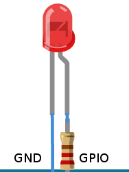
Anode goes to the resistor (long pin). Cathode goes to ground (short pin)
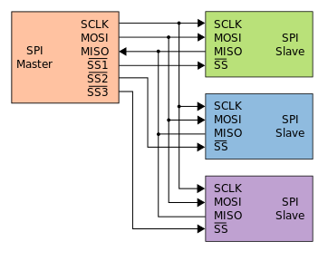
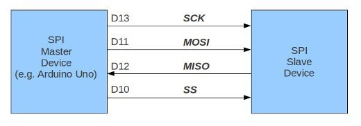
A few words on SPI
- Four-wire serial bus
- SCLK - serial clock
- MOSI (master output slave input)
- MISO (master input slave output)
- SS (slave select)
- One master, multiple slaves
- Clock rate 100+ MHz
- Used for flash, eeprom, sensors, ... and even SD cards
Example on wiring
nRF24L01+ features
- Worldwide 2.4GHz ISM band operation
- Up to 2Mbps on air data rate
- Automatic packet handling
- Ultra low power operation
- SPI
- Applications: Mouse, keyboards, remotes, RF remote controls, ...
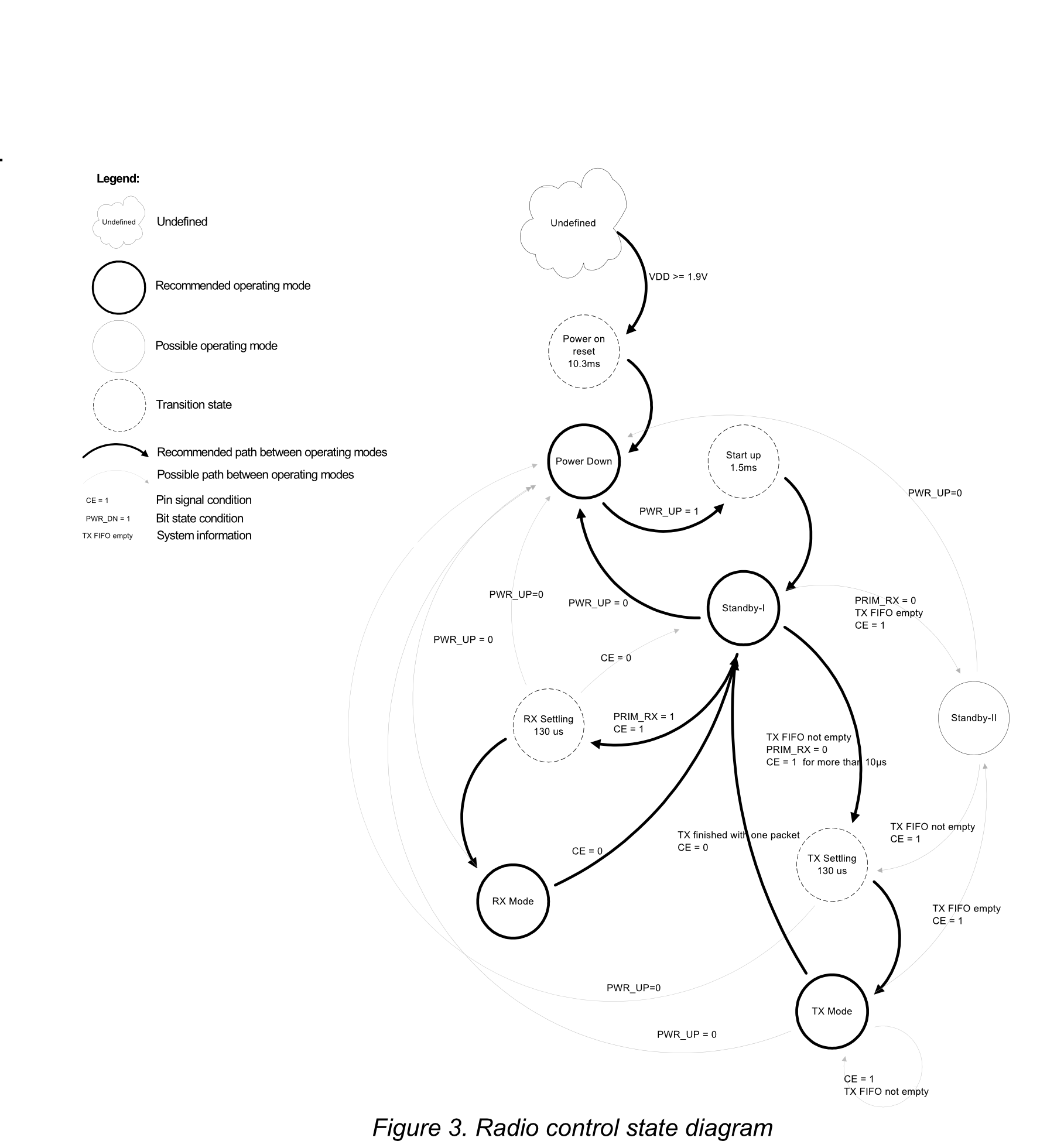
nRF24L01+ state diagram
nRF24L01+ registers
Chip is controlled by a number of registers
From nRF24L01.h
#define CONFIG      0x00
#define EN_AA       0x01
#define EN_RXADDR   0x02
#define SETUP_AW    0x03
#define SETUP_RETR  0x04
#define RF_CH       0x05
...
Let us check section 9 of the datasheet
nRF24L01+ SPI interface
Let us check section 8.3.1 of the datasheet
- Every new command must be started by a high to low transition on CSN
- In parallel to the SPI command word applied on the MOSI pin, the STATUS register is shifted serially out on the MISO pin
-
The serial shifting SPI commands is in the following format:
<Command word: MSBit to LSBit (one byte)>
<Data bytes: LSByte to MSByte, MSBit in each byte first>
SPI interface code example
uint8_t RF24::read_register(uint8_t reg,
                            uint8_t* buf,
                            uint8_t len)
{
  uint8_t status;

  csn(LOW);

  status = spi->transfer( R_REGISTER | ( REGISTER_MASK & reg ) );

  while ( len-- )
    *buf++ = spi->transfer(0xff);

  csn(HIGH);

  return status;
}
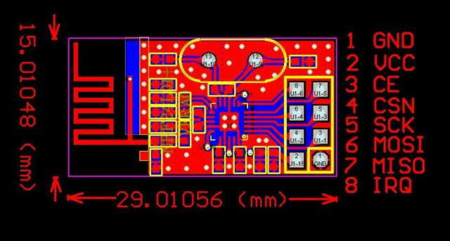
nRF24L01+ PCB pinout
Enable SPI on Pi - 1
Enable SPI kernel module
/etc/modprobe.d/raspi-blacklist.conf
You should end up with:
pi@raspberrypi /etc/modprobe.d $ ls -la /dev/spidev0.*
crw-rw---T 1 root spi 153, 0 Jan  1  1970 /dev/spidev0.0
crw-rw---T 1 root spi 153, 1 Jan  1  1970 /dev/spidev0.1
Enable SPI on Pi - 2
Make a SPI group and add yourself:
sudo groupadd -f --system spi
sudo /bin/sh -c 'echo ''SUBSYSTEM==\"spidev\", GROUP=\"spi\"'' >/etc/udev/rules.d/90-spi.rules'
sudo adduser $USER spi
Hook it up
Time to connect the pieces
- CE goes on GPIO 25
- CSN goes on GPIO 8
git clone software from:
https://github.com/openspaceaarhus/Datalogforeningen-workshop.git
SPI software
Library:
cd rpi/librf24

make

sudo make install
Examples:
cd rpi/librf24/examples

make
Expected output from 'pingtest ping'
SPI device	 = /dev/spidev0.0
SPI speed	 = 8000000
CE GPIO	 = 25
STATUS		 = 0x0e RX_DR=0 TX_DS=0 MAX_RT=0 RX_P_NO=7 TX_FULL=0
RX_ADDR_P0-1	 = 0xf0f0f0f0e1 0xf0f0f0f0d2
RX_ADDR_P2-5	 = 0xc3 0xc4 0xc5 0xc6
TX_ADDR		 = 0xf0f0f0f0e1
RX_PW_P0-6	 = 0x20 0x20 0x00 0x00 0x00 0x00
EN_AA		 = 0x00
EN_RXADDR	 = 0x03
RF_CH		 = 0x4c
RF_SETUP	 = 0x07
CONFIG		 = 0x0f
DYNPD/FEATURE	 = 0x00 0x00
Data Rate	 = 1MBPS
Model		 = nRF24L01+
...
Getting data transferred
Set the channel to:your age since the epoch % 128
Try to do a ping/pong with somebody else
Chip supports Auto Ack payloads.
Play with enableAckPayload, writeAckPayload and isAckPayloadAvailable
For the hackers
Find the message that our beacon is sending
- Beacon transmits at 250KBPS
- Use
scanner.cppto find the carrier - The time listening for a carrier must be raised
- Modify
pingtest.cppto receive the message - Disable auto Ack
For the real hackers
- 'Bit bang' the SPI interface by re-writing spi.cpp
- Remember to disable spi-bcm2708
- DON'T TRY TO CONFIGURE ANY INPUTS TO FUNCTION AS OUTPUTS
- Suggestion: Make use of gpio.cpp/gpio.h
- Check 8.3.2 in the datasheet for SPI operation
Arduino - what is that?
Arduino Uno
- ATmega328 with 32 KB flash and 2 KB SRAM
- 8 bits!
- 14 digital and 6 analog I/O pins
- SPI and I2C
- On-board bootloader for easy programming
- Can be programmed in C++
Arduino simplicity - blink the LED
#define LED_PIN 13

void setup () {
  pinMode (LED_PIN, OUTPUT); // Enable pin 13 for digital output
}

void loop () {
  digitalWrite (LED_PIN, HIGH); // Turn on the LED
  delay (1000);
  digitalWrite (LED_PIN, LOW); // Turn off the LED
  delay (1000);
}
Arduino Uno - SPI
SPI on the Arduino _UNO_
D10 == SS == CSN and we use D9 for CE
Arduino Leonardo - SPI
On the Arduino Leonardo SPI is on the ICSP header
- ICSP PIN 1 = MISO
- ICSP PIN 3 = SCK
- ICSP PIN 4 = MOSI
PIN 1 is the one with the small dot next to it
Arduino - Makefile
ARDUINO_DIR  = /usr/share/arduino

TARGET       = pingpair
ARDUINO_LIBS = SPI

BOARD_TAG    = uno
ARDUINO_PORT = /dev/cu.usb*

ARDUINO_PORT =/dev/ttyACM0
ARD_PROG = -c stk500v2

include /usr/share/arduino/Arduino.mk
Type make to build and make upload to write to the Arduino
Arduino - software details
- avr-gcc for compilation
- avrdude for writing the software (Arduino contains a bootloader)
- You can use the UI to make life easier in the beginning
sketchbook/pingpair/pingpair.ino
sketchbook/libraries/nrf24/printf.h
sketchbook/libraries/nrf24/RF24.h
sketchbook/libraries/nrf24/nRF24L01.h
sketchbook/libraries/nrf24/RF24.cpp
sketchbook/libraries/nrf24/RF24_config.h